ETCO’s Engineering Guides provide important electrical terminal performance and quality information for manufacturers. Click through for answers to your engineering and manufacturing questions.
Ul 310 is a safety standard developed to evaluate performance of quick connect electrical terminals. ETCO engineers simulate UL 310 testing to qualify terminal performances to industry requirements. The test outlined here exposes mated sets of terminals forming a circuit to cyclical periods of energization.
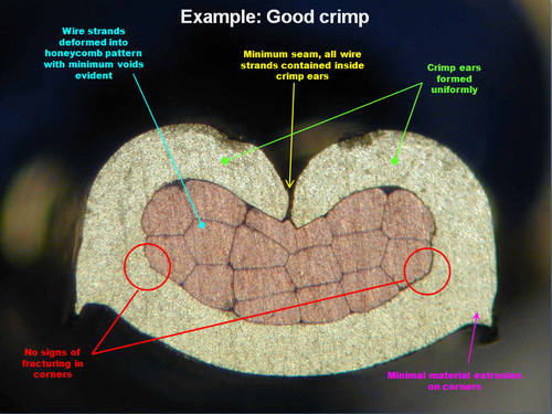
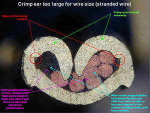
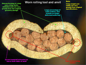
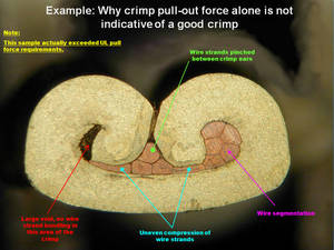
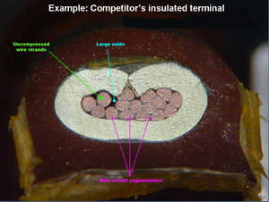
When it comes to wiring and providing an acceptable crimp for connectors ETCO always comes out on top. Our connectors are engineered with efficiency, safety, quality and durability in mind. There’s nothing worse than a crimp with wires jutting out causing possible fire hazards and connectivity losses. ETCO has never comprised on quality. The gallery below illustrates the differences between our crimps and competitor crimps.
| Conductor Size | Assigned maximum | Static-heating | |
| AWG or kcmil | mm2 | ampere rating | test current |
| 28 | 0.08 | – | 3.5 |
| 26 | 0.13 | 3.5 | |
| 24 | 0.2 | 7 | |
| 22 | 0.324 | 9 | |
| 20 | 0.519 | – | 12 |
| 18 | 0.823 | 17 | |
| 16 | 1.31 | – | 18 |
| 14 | 2.08 | 15 | [20]30 |
| 12 | 3.31 | 20 | [25]35 |
| 10 | 5.261 | 30 | [40]50 |
| 8 | 8.367 | 50 | 70 |
| 6 | 13.3 | 65 | 95 |
| 4 | 21.15 | 85 | 125 |
| Wire Size | Static Heating Test | Heat-Cycling Test | |
| Wire Size | mm2 | current amperes | current amperes |
| AWG | |||
| 18 | 0.82 | 10 | 20 |
| 16 | 1.3 | 13 | 25 |
| 14 | 2.1 | 18 | 32 |
| 12 | 3.3 | 25 | 37 |
| 10 | 5.3 | 30 | 45 |
| Wire Size | Temperature | Heat-Cycling | |||
| AWG | mm2 | 0.110, 0.125 inch | All others | 0.110, 0.125 inch terminals | All other |
| (2.8mm), (3.2mm) terminals | (2.8mm), (3.2mm) | ||||
| 22 | 0.32 | 2 | 3 | 4 | 6 |
| 20 | 0.52 | 3 | 4 | 6 | 8 |
| 8 | 0.82 | 4 | 7 | 8 | 14 |
| 16 | 1.3 | 5 | 10 | 10 | 20 |
| 14 | 2.1 | 15 | 30 | ||
| 12 | 3.3 | 20 | 40 | ||
| 10 | 5.3 | 24 | 48 | ||
The typical average force observed when inserting/extracting a standard NEMA DC2 male test tab into a standard ETCO disconnect while using an ETCO insertion/extraction force gauge to standard operating procedures is shown below:
| Male Size | First Insertion | First Extraction | Sixth Extraction |
| Width (mm) | lbs. (N) | lbs. (N) | Ibs. (N) |
| * .250″ (6.35) | 8.5 (37.81) | 7.5 (33.36) | 5.5 (24.47) |
| .187″ (4.75) | 6.0 (26.78) | 10.0 (44.64) | 6.0 (26.78) |
| .110″ (2.79) | 6.0 (26.98) | 7.0 (31.25) | 4.0 (17.85) |
*Male test tab with recessed dimple for the detend feature, versus through hole on all others.
The minimum force required to separate the wire from the wire crimp ear with the insulation ear, if present, rendered inoperative will be as follows:
In some cases ETCO will recommend higher pullout forces to increase conductivity. ETCO will recommend crimp height to accomplish best all around crimp performance.
| Size Of Conductor | Pullout Force | Pounds | Newtons |
| AWG | mm2 | ||
| 28 | 0.08 | 2 | 8.9 |
| 26 | 0.13 | 3 | 13.4 |
| 24 | 0.2 | 5 | 22.3 |
| 22 | 0.324 | 8 | 35.6 |
| 20 | 0.507 | 13 | 57.7 |
| 18 | 0.823 | 20 | 89 |
| 16 | 1.31 | 30 | 133.5 |
| 14 | 2.08 | 50 | 222.5 |
| 12 | 3.31 | 70 | 311.5 |
| 10 | 5.261 | 80 | 356 |
| 8 | 8.367 | 90 | 400.5 |
| 6 | 13.3 | 100 | 455 |
| 4 | 21.15 | 140 | 623 |
Measuring Crimp Height: Crimp height must be measured with the spindle and anvil of a micrometer, centered against the bottom and the top of the crimp respectively and between the ribs on the bottom of the crimp, if applicable.
ETCO continually test products for quality, reliability, and manufacturing efficiency. Our engineering team often publishe\s their results in White Papers. Topics include:

About ETCO
Product Catalog
Receive a Quote

Note that the compression power was a Ford Air Brake so the crimp was squeezed (not smacked) to provide a superior connection.